
$10 DIY Wifi Door Sensor
SimpleIOThings is the easiest and cheapest way to build DIY IoT projects with no coding or soldering required!
This tutorial will teach you how to build a Wifi Door Sensor for about $10 dollars. You won’t have to code anything, and you won’t have to solder or buy expensive electronics equipment. Any services you are asked to use will be 100% free. Its that easy. Lets get started!
Some doors are meant to stay closed. For example your freezer door needs to stay closed to keep your energy bills down. Pet owners need to keep the door closed so their four-legged/winged companions don’t wander outside. Whatever door you need to keep an eye on, a wifi enabled door sensor can help you send a smartphone notification, SMS, email, and even an automated phone call when its been open too long.
The cool thing is, you can build one of these for about 10 dollars. I know you’ve seen these types of tutorials on the internet before, and usually they say something like, just buy a breadboard, soldering iron, breakout board, serial adapter, etc. etc. and after you’ve spent about $50 dollars you can build a cheap Internet of Things (IoT) device. Well, sorry internet. We nerds sometimes forget that most people don’t really have these things lying around. That’s why I built this website around the idea that IoT devices can be built without coding knowledge, soldering, or complicated prototyping.
STEP 1: Gather Your Materials
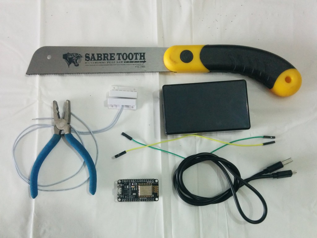
Its a good idea to buy your parts first because on the sites where the merchandise is cheapest (Ebay or Aliexpress) shipping times are rather lengthy. Depending on where you live in the world, it might take some time for your components to reach you so its better to do this sooner in the process than later. Here’s a list of things needed for this project. FYI, I’ve included some affiliate links to the cheaper places you could buy these components. I’ve done my best to ensure the ads display the lowest price goods that are relevant to this project, and if you buy through them you’ll be helping me maintain this site. Thanks! 😉
Required Components:
(FYI, if you’re just seeing text below with no images, its probably because you have an adblocker on. I know ads suck, but in this case they were actually a creative way to continuously update the page with the lowest cost parts. Prices change, so if I used static links and pics, the link would quickly become outdated. Please consider turning off adblock for this site for the best experience.)
ESP8266 Development Board (~$3 @ AliExpress; Nov 2017)
AliExpress.com ESP8266 Development Board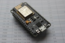
DIY Project Box Enclosure 100x60x25mm
Female to Female Jumper Wires
MicroUSB cable (10′ Cable Recommended)
USB Wall Charger
Project Specific Parts
Wifi Door Sensor
MC-38 Sensor (~$2 for 1 sensor, less if you buy in bulk; Nov 2015)
Suggested Tools:
These are tools recommended to build the IoT device in this tutorial.
Pliers
Hacksaw
Great. Now like I said, its gonna take a while for your stuff to get to you, so in the meantime lets setup some digital infrastructure that we can use once your stuff arrives.
Note: This is our third tutorial! You should be noticing a pattern by now, which is that steps 2 – 4 are pretty much the same for every device. If you already know how to do all the basic stuff, skip to step 5, where I start to talk about some stuff specific to this project.
STEP 2: Setup Your IFTTT Account & Recipes
The Wifi Door Sensor, and all of the devices on SimpleIOThings, uses a service called If This Then That (IFTTT). You can find a full tutorial on how to sign up and configure digital communications for your IoT devices in the Getting Started: Setup IFTTT post. Once you completed it, you should have completed the following:
- Signed up for an IFTTT account
- Downloaded the IFTTT App
- Connected to the Maker Channel
- Recorded your Maker Key
- Organized Maker Events (Triggers) that lead to IFTTT Actions.
Okay! We’ve got some really nifty digital infrastructure setup for your project. Soooooo…its gonna take a while before you get all this stuff…so its probably best to bookmark this page and come back after it’s all arrived. See you in a few weeks!
STEP 3: Install Firmware to your Dev Board
Oh hi there! Welcome back. I know its been a while. Maybe the seasons changed in your part of the world. Governments may have risen, switched hands, entered alliances, broken alliances, fallen, and then risen again. Yea…it takes a while to get your stuff. But now that it’s here, lets start building!
You can find a full tutorial on how to load firmware onto your ESP8266 Development Board on the Getting Started: Setup ESP8266 Dev Board post. After you’re done with this tutorial you should have completed the following.
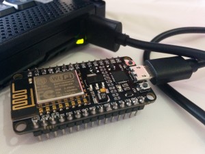
- Connect your ESP8266 Dev Board and Install Drivers
- Load Firmware onto Dev Board using ESP8266Flasher.exe.
- Connect to Dev Board using LuaLoader.
STEP 4: Install Sensor Specific Software to your Dev Board
Great! Now your dev board speaks Lua and its ready to start communicating with the world and run programs. Now it just needs specific instructions or programs to be useful for your specific use case. Lucky for you, I’ve already written the programs needed to get your device up and running. Full instructions on how to program your device with specific settings for your use case can be found on the Getting Started: Loading Device Software Via LuaLoader tutorial page. In this tutorial you should have completed the following:
- Download the latest SimpleIOThings.zip file from the Downloads page.
- Extracted the zip file and run the SensorSetup.bat file.
- Input your information into the command prompt to enter user and device specific information (IFTTT Maker Key, the Maker Event name, the device’s location info, etc).
- Entered “2” for the Sensor Type Number, identifying this sensor as a “continuous read” sensor (i.e. one that reads the sensor’s current state, and triggers an alert if a specific state [like an open door] is detected for more than a threshold determined number of seconds).
- Enter input thresholds, input timeouts, and interval between notifications as prompted.
- Uploaded device specific files to your ESP8266 Development Board using LuaLoader.
- Set the Wifi Network Name and Password for your ESP8266 Development Board.
STEP 5: Modding Your Enclosure
All the way back in step 1, we talked about gathering materials. Now that you have everything in hand and your board is programmed, get all your materials together in one space.
Some suggestions on how to mod your enclosure can be found here at Getting Started (5): Modding Your Enclosure. After completing this tutorial you should have completed the following:
- Created an opening in the rear of the enclosure for the microusb power cable.
- Created an opening in the front of the enclosure for the jumper wires.
STEP 6: Build the Door Sensor
Now go ahead and unplug your dev board (there is almost no electrical danger to you from touching the dev board while plugged in, but might as well err on the side of safety).
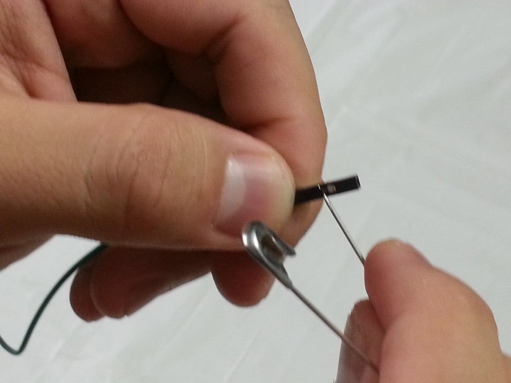
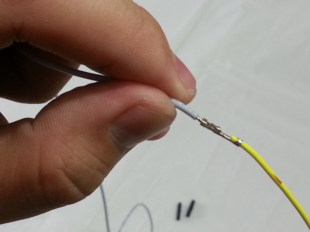
Grab your two jumper wires. You can see that at the end of each wire is a plastic housing covering some metal. We’re gonna remove that plastic housing. Grab a needle or safety pin, and find a small tab in the plastic housing. Lift up on the plastic tab. Once lifted up, you should be able to smoothly remove the wire from the plastic housing.
Now, grab the MC38 sensor that you bought. Note that there are two halves to it. The side with the wires is the actual sensor, while the side without wires is actually just an enclosed magnet. The sensor half contains something known as a reed switch. A reed switch is either normally open or normally closed, and when it comes in range of a magnet, the switch inside will close or open to break or create a circuit.
Okay, so grab the sensor, and then note that the exposed wires. If the wires aren’t exposed, you’ll need to strip off some of the wire insulation. Once you’ve removed the jumper wire housings, and grabbed the MC38 sensor wires, the ends of the four wires should look like this.

One of the guarantees I make at the beginning of each tutorial is that the project won’t require any soldering. Since we have to connect these female jumper wires to these exposed sensor wires, we’re gonna use a technique called “crimping.” Crimping is a way to join wires by using a pliable metal housing that you can compress with pliers to create a firm connection.
Insert your exposed sensor wire end into the remaining metal housing end (the part that was under your plastic housing. It should look like this:
Once the wire is fully inserted, use your pliers to “crimp” down on the metal housing, but not that hard! Hard enough to bend the metal to create a good connection, but not so hard it cuts through the metal housing and the wire. It should look like this:
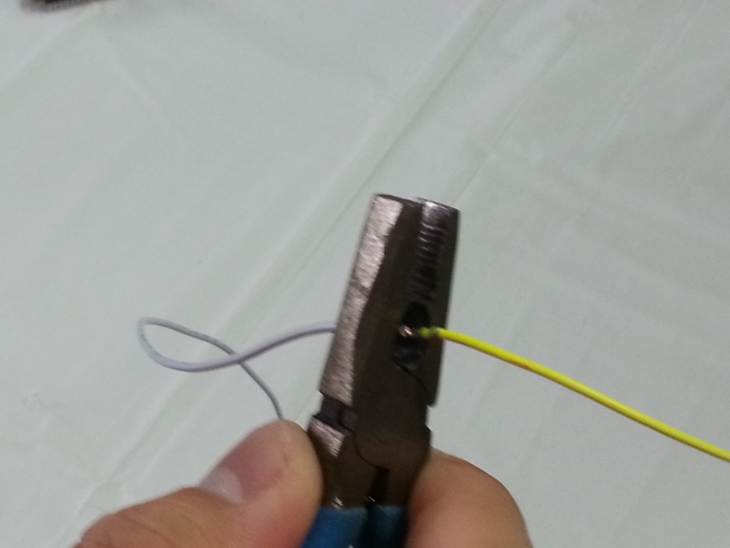
Once your wires are successfully crimped, we also want to make sure that the two metal housings on separate wires do not touch one another. To do this, use duct tape or scotch tape to insulate your exposed wires.

Now grab your dev board, and observe the names of the pins on the board. Go ahead and plug your jumper wires into the “GND” and “D2” pins on the right hand side. It should look like this:
![22627004201_f05864362c_k[1]](http://www.simpleiothings.com/wp-content/uploads/2015/11/22627004201_f05864362c_k1-1024x768.jpg)
Everything should now look like this:

Just a quick note for those of you who are interested in the electronics. When setup this way the door sensor, when opened, is acting as a bridge between the D2 pin and the electric ground (-). That way when the magnet is pulled away from the sensor, it grounds the D2 pin, registering a change in electrical signal which the chip detects as a sensor input. Pretty cool! Great, the electronics are all setup. Pretty simple right?
Alright, now you can put your electronics into the enclosure. Plug your usb cable into the dev board, and make sure your jumper wires are well positioned before you close the project box.

And we’re done!
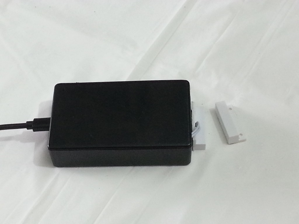
Your sensor should now be fully operational. Give it a test run by separating and it should trigger whatever you’ve set it up to do, whether that’s a smartphone notification, SMS, phone call, email, etc.
I installed mine on my fridge. Every once and a while I position my frozen foods poorly. This pushes open the fridge door, everything in my fridge ends up thawing overnight. I built this sensor to tell me when my fridge door is open too long, but you can use it for your front door, a window, etc.

I hope you enjoyed building a super simple Internet of Things device. Hopefully you will be able to use it for something useful, or use it to do something fun. If you enjoyed this tutorial, consider donating at the link below. Thanks for reading!
SimpleIOThings • November 14, 2015
Tom_Neverwinter March 27, 2016 - 5:19 am
Your site is easily the best iot site I’ve seen. no proprietary bs, no use our shitty architecture. I appreciate the barebones, Modular and functionalist system. now the last device I need to get running is a mailbox sensor with temp and light w/ maybe a few other sensors run from battery and solar.
Paul August 13, 2016 - 1:22 am
Hi
The door sensor project looks great and is just what I need. I have ordered all the parts and they have arrived. It now looks like your instructions for programming the board are for a PC. Can I do this on a Mac?
Look forward to some advice on this.
Many thanks for the work you have done on this.
Paul
SimpleIOThings October 18, 2017 - 5:14 am
Hey Paul, I would recommend using a Windows virtual PC to load firmware and software onto the board.
David Lamb September 5, 2016 - 4:39 am
This is pretty cool. Would it be possible to add wires on the board from a wired garage opener and update the code to trigger open/close.
I’m thinking I could use IFTTT to integrate with this, especially with the maker channel, and potentially take a $10-$15 iot to automate my garage beyond knowing it’s open/close but also being able to change its state.
Michael Fenton September 12, 2016 - 6:39 pm
Hi,
Brilliant project – I recently left my freezer door open overnight and wanted to by a door switch that would alert me . Built the device but struggling to get to Alert me via sms . Set up ifttt account with recipe and input my mobile no and it sent me the text which i verified . Have you go any pointers of what to look for . The switch works as I can see the sensor inputs in the Lualoader software . What is the notification time in minutes for the default settings . I live in the uk so wasnt sure if this had anything to do with the problem
Thanks in advance
Jacob September 13, 2016 - 8:50 pm
Hi that setup seems pretty cool but im wondering is there any way to know the status of the at any time. let says I install it on my garage door can go on the IP of the wifi board and know if my garage door is open in real time?
Aaron Peterson October 15, 2016 - 11:24 am
Now we need to make it have good life when running off of a battery.
I think we could do that by making the device power on when the relay is triggered. (if the person wants the device to be transmitting when the door is closed, then just use a the opposite type of relay, or many relays have a normally open gate and a normally closed gate…
We could also make it so that the device stays on for a bit after the gate is closed to transmit the door is closed signal.. Well then, we should use the normally open and normally closed gates on the relay, (magnetically controlled switch) and have the device wake up for just long enough to transmit the change of state, then power off. How to make it not use any power when it is off though?
If we have an always running but of logic, we could use just one of the normally open or normally closed lines…
SimpleIOThings October 9, 2017 - 4:31 am
Yea there is definitely a battery friendly solution. When I have more time for my hobbies I’m gonna give the code a hard relook. 🙂
Larry Elliott December 14, 2016 - 1:15 pm
Would it be possible to put multiple door sensors on the same board?
Steve December 20, 2016 - 6:59 pm
Hi,
I’m wondering how easy it would be to connect two door sensors to the board. What would the wiring look like?
Thanks 🙂
Iwantmyiot February 6, 2017 - 10:57 pm
Awesome site and pertinent information!
Smoke alarm and this will be my next projects. Thank you for sharing.
Some general questions…
1) Can this sensor be picked up/detected by Homeassistant?
2) Also regarding this project can this be used/modded to be a panic button, and trigger other IoTs?
3) lastly, can these wifi devices be battery powered (and stay like that for months?) if not could they be modded to?
Keep up the good work!
Ken February 22, 2017 - 5:07 pm
I am really new to this. The programming part still has me confused along with
what the door switch is suppose to do.
I was thinking of using a few WiFi smart plugs to control a relay that would open and close
my garage door. That part is easy using the app that comes with the device and a relay that gets powered by a 120ac to 5 volt d.c. supply. I wanted some
type of email confirmation whenever the door is opened or closed.
Again I am new here so I might have missed it .. how does the device described here report
the status of the door opened or closed.
Thanks,
Ken
Luke March 17, 2017 - 3:21 pm
Just wondering how you settings you used for the Sensor setup?
I have tried to use the stock standard bat file examples and it doesn’t seem to do anything for the sensor.
The example used the following
alertDelay: 30
timerThreshold: 10
sensorThreshold: 1000
Can you confirm that is what you used?
Thanks,
Luke
John Brannen March 23, 2017 - 4:57 pm
Great project!!! I built one and have it working, but am having a little issue. I am using this to notify me if my detached workshop door is opened. Kind of as a pseudo alarm. The problem I have is that notifications to my phone sometimes have significant lag. It seems that if the sensor is not triggered for some time that the time from activation to receipt of the notification can take up to 10 minutes. If there has been a recent activation, the notification only takes seconds, but the first notification after a period of inactivity takes a long time. Is there anything that can be done to reduce this?
.
Also, I have a second ESP8266 that I want to experiment with and create a similar sensor that would send the notification of the door opened, but also be able to be pinged from my phone to check the state (ie: open or closed). Any help getting me started down this road would be greatly appreciated. Alternately, setting it up so that it would send a notification any time the state changes. For example “The XXX_Door was opened” and “The XXX_Door was closed”
.
Thank You, Thank You, Thank You for the great project and write-up.
dan May 6, 2017 - 3:00 pm
for some reason, it’s working in reverse for me. when the door opens, nothing happens. when the door closes, it triggers the event.
D2 to GND has continuity through the switch when the magnet is next to it.
continuity is lost from D2 to GND through the switch when the magnet is away.
so with the switch together(door closed), D2 is shorted to GND so it goes LOW. when the switch is separated (door open), D2 is open circuit to GND so it goes HIGH.
i can get it to work if i connect 3.3v to the reed switch, reed switch to D2 and put a 15k resistor between D2 and GND.
any way to get a status message every time there is a change from either door open to door closed and door closed to to door open? right now i can only get a message for one, not both.
Brad Plett June 5, 2017 - 6:56 am
It seems to me that either there is a bug in it, or the generic sensor software provided on the downloads page (simpleiothings.zip) isn’t particularly well suited to a door ajar application. Of course, this may also be due to the fact that the file I should be downloading (SimpleIOThingsDoorSensor.zip) doesn’t appear to be there.
For one thing, with the software provided, it only senses the door opening, not the door closing. If we can only sense the door opening, we’ll never know how long it’s been open.
Chris June 22, 2017 - 7:09 pm
Hey there.
I’m planning to set this up at home. Since I’ve got three doors next to each other, do you think it would be possible to use multiple MC-38 on just one ESP? I’m a total noob with these stuff, any help would be greatly appreciated!
Regards,
Chris.
SimpleIOThings October 9, 2017 - 5:04 am
It is possible but not with the current code base. Basically you’d need to rewrite the LUA code to monitor multiple GPIO pins for changes. Give it a shot!
Mario Beaulieu July 11, 2017 - 5:03 pm
Hi,
Thanks for this tutorial. This is very close to what I’m trying to achieve, which is to build (or buy) cheap switches that would communicate to Homekit or Homebridge.
I have many devices connected to Homekit and Homebridge (on my Raspberry Pi). Now, I would like to “know” if a window is open or close, etc. So I need cheap intelligent switches.
Is it possible to connect your solution to homebridge instead of going thru IFTTT?
Thanks a lot
Mario
Salim M August 17, 2017 - 1:43 am
How could this be easily modified so that it has two magnet door sensors?
One for the freezer and one for the fridge, using the same housing and dev board, just adding a second magnet sensor. Any suggestions? Thanks.
SimpleIOThings October 9, 2017 - 4:22 am
This can be done but you’d have to rewrite the code to listen for changes in electrical signals on more than one GPIO pin. Its definitely doable. Take a look in the sensor software code and see if its something you can tinker with! 🙂
Steven August 19, 2017 - 5:36 am
HI, thanks so much for this info. I’ve followed through all the steps but I’m not sure if I’m doing something wrong?
My problem is this:
The door sensor triggers when the sensor ‘reconnects’, not when it has been disconnected after X number of seconds.
1. Sensors are together (magnet engaged)
2. Logs say Listening for Sensor Inputs
3. I move the sensors apart
4. Logs still say Listening for Sensor Inputs
5. I put the sensors back together
6. Logs say (1) sensor inputs counted
I guess what I’m hoping for this to do is for the sensor to trigger when the sensors are moved apart. Am I missing something?
Thanks
SimpleIOThings October 10, 2017 - 3:22 am
Hey Steven,
Looks like something got goofed up with a recent code update. Sorry about this. I’ll be working on a new solution for the door sensor.
SimpleIOThings October 22, 2017 - 3:00 am
Hey Steven, try the latest software via the download link. The software now runs two different types of code based on whether or not its detecting an interrupt or continuously reading the pin state each second. It should work well with the door sensor now.
jan September 21, 2017 - 6:14 pm
is it possible you can make a video/pictures on how to proceed on the SimpleIOThingsDoorSensor.zip, specifically what info goes into the maker account and so on, and perhaps also on the lua loader.
Thank you…. great project
Www.Topicemakers.Net October 6, 2017 - 10:19 am
It’s a shame you don’t have a donate button! I’d most
certainly donate to this excellent blog! I suppose for now
i’ll settle for bookmarking and adding your RSS feed to my Google
account. I look forward to new updates and will talk about this blog with my
Facebook group. Talk soon!
SimpleIOThings October 9, 2017 - 4:01 am
We do indeed have a donate button at the bottom if interested. Glad you enjoyed the blog. 🙂
sandeep October 29, 2017 - 4:49 am
Excellent writeup
I’ve got the sensor now.
what is the maker channel you have suggested.
i tried to search in IFTTT but could find only Wemo Coffee maker there.
SimpleIOThings November 1, 2017 - 9:28 pm
Hey Sandeep, glad you enjoyed the writeup! The Maker Channel at IFTTT has gone under some rebranding recently, and is now called WebHooks. Other than the name change, the service works exactly the same. Take a look at the rebranded service here: https://ifttt.com/maker_webhooks.
Sam Ryan November 3, 2017 - 4:26 am
Hi mate, I’m having a bit of trouble. I’ve set up the device, but when I test the hardware, nothing happens, webhooks does not get a notification, but when I test the URL it fires off just fine.
Any ideas what might have gone wrong?
SimpleIOThings November 4, 2017 - 5:17 am
Hi there. A few things I would do to trouble shoot are: double check your internet connection, make sure you are connected to the right pins, make sure your maker key is EXACTLY the same as online, make sure your event name exactly corresponds to the event name you registered on IFTTT. Let me know if you’re able to get it up and running.
ANDY November 4, 2017 - 6:20 pm
In your picture it shows the lua programmer as 2 GPIO4, for mine is showing something different, 3 GPIO0, and I do not have yours as an option is that a problem?
SimpleIOThings November 4, 2017 - 6:59 pm
Hey Andy. That shouldn’t be a problem. The section in the LuaLoader program that reads and sets GPIO pins is not used in the tutorial. The GPIO pin setup and reading all happens through the lua code files which are uploaded to the development board. Try following the tutorial all the way through and see if your device works.
Andy November 5, 2017 - 4:17 am
Worked like a charm. Thanks for the detailed instructions and the quick response to my questions earlier.
I am looking for an alteration to the code, but I do not program. I would be willing to donate to the page for your work ahead of time. I would just need to know approximately how much of a donation I would need to make to make it worth your time. I need the sensor to send an alert upon status change. i.e. trigger an event when opened, then monitor and trigger alert when closed.
Incase anyone was interested, I use the sensor to trigger Samsung Smartthings workflows. Basically when the sensor is open for over 30 seconds it sends the trigger to ifttt. My applet in ifttt is setup to turn on a virtual switch in Smartthings. I then run all of my rules and alerts against that virtual switch. Now if I could only get the sensor to send an alert on closing I would be golden. I use this switch due to the fact my garage is too far to have ZigBee or Z Wave sensors work. My wifi reaches no problem.
Sincerely,
Andy
SimpleIOThings November 6, 2017 - 8:01 pm
Hey Andy,
Great to hear that you got the sensor to work with Samsung Smart Things! It just goes to show you how adaptable and flexible these devices can be when tied to IFTTT. With a little creativity, these DIY devices can perform scores of actions when connected to the right IoT recipes.
Let me think about your specific garage door use case and see if there’s an elegant programming solution. I can’t make any promises, but I will definitely take a second look at that code.
ANDY November 8, 2017 - 6:02 am
I found a guy in Peru who knew Lua and was willing to work with me. After 4 hours of work and a few $ we finally finished the code for the garage door. It works amazingly.
SimpleIOThings November 8, 2017 - 7:04 am
Hey that’s awesome! Sounds like you’ve had a really interesting project. Let me know if the comments in the lua code files helped your programmer to understand how the software worked, and if there’s anything you’d be willing to share about the method you used to trigger the door closure notification.
Andy Mazur November 8, 2017 - 9:28 pm
Yes, we used a lot of your code and just edited what was needed. I will send you the code we created. You could post it on your site if you would like. He was the brains behind it. I was just the momentum to get it done. Let me know the best way to send it to you.
SimpleIOThings November 9, 2017 - 3:06 am
Hi, please send it to simpleiothings@gmail.com. Also, please send me the name of programmer if he would like to be credited. Thanks!
Sam January 12, 2018 - 4:30 pm
Andy, I am also interested in your code can you email it to simpleiothings@gmail.com so it can be shared?
Nigel December 31, 2017 - 11:29 am
Hi, Thanks for inspiring us. A great write-up & instructions.
I have got it working, even though it took a few hours to get everything right but I wasn’t helped by what appears to be a firmware problem.
Any help diagnosing the problem would be appreciated.
I purchased a ‘NodeMcu Lua WIFI Internet Things development board based ESP8266 CP2102’ from Amazon.
Using nodemcu-build.com I downloaded the ‘Master’ firmware ‘nodemcu-master-7-modules-2017-12-30-11-35-54-integer.bin’ using the standard options file/GPIO/net/node/timer/UART/WiFi, and successfully programmed the board.
I then downloaded ‘simpleiothings_16Oct2017’ from http://www.simpleiothings.com and successfully programmed that through the LuaLoader.
When running the program a PANIC occurs in 2_ifttt.lua around the comm:dns section, and it is caused by the comm:connect causing a second connection. I tried for hours to fix the code but not being a native Lua programmer I was unable to find a solution.
I then downloaded the firmware ‘1.5.4.1-final (frozen, for 512KB modules)’ and programmed that, followed by re-uploading the Lua code. Now it works!!!!!
It appears that the latest firmware doesn’t work?
Also the setwifi.lua wasn’t working with the latest firmware, I haven’t yet tried it with the older firmware.
Any ideas?
Nigel
SimpleIOThings January 4, 2018 - 3:20 am
Hey Nigel. Sorry you’re running into some trouble with the firmware. It seems that the firmware from the builder can be a hit or miss, so I’ve updated the tutorial to refer back to the GitHub page. Try loading the firmware from https://github.com/nodemcu/nodemcu-firmware/releases. Towards the bottom of the page, you’ll see the 0.9.6-dev_20150704 build of the firmware. Download the “integer” version and load it onto your board using the NodeMCU flasher. Let us know how that goes.
SetWifi doesn’t work with all networks. I recommend setting the AP using the built in functionality in LuaLoader, as that seems to work the best. You’ll see an option to set that in your LuaLoader software on the right hand side.
Hope you’re able to get your project up and running. Tell us if you were successful!
Valter January 8, 2018 - 6:35 pm
Good job, thank you hard work.
For me everything was perfect, works great.
I thinking in use in my garage door, because I had some events that opened the garage door mysteriously.
I know it’s possible to use another sensor pin to remotely close or open the Garage door, but I’m totally noob in programation. There is a chance to you include this feature in future ?
Thanks.
Valter
SimpleIOThings January 11, 2018 - 5:37 am
Hey Valter, Glad the sensor works great for you.
With regards to remote opening and closing of the garage door, this is not a supported feature for the devices on this website. It would require an entirely different set of code. The current program listens to the sensor for feedback and sends messages to the web. The code you want would need to listen to the web for commands (opposite of current code), and send an electrical signal to a motor (like the one that powers the garage door). Its totally doable, but I’m currently not developing any remote control features at this time.
Let us know what you find out using the sensor! I wonder if a strong wind is opening your garage door, or maybe a small animal.
Stephen Miller January 31, 2018 - 3:47 am
A great first IOT DIY project. Got everything to work with no problems. Going to build upon this to make into a remote sensor for my mailbox.
James Wardstrom April 16, 2018 - 8:15 pm
Great Project!
Had it all built and working the first day but now I get no notifications any more
any ideas what could cause it to stop working?
Is there something simple in the coding that can repair this issue?
James Wardstrom April 19, 2018 - 3:57 pm
All good again I think it was a power supply issue.
Florian K April 26, 2018 - 12:15 am
Hello,
Thanks for that great receipt – I changed the way of use and connected a water level sensor so I get an email if water level in my water tonne get’s low!
Works perfectly,
Flo
Mike June 3, 2018 - 2:43 pm
For all those interested in monitoring two or more doors, my simple solution was to wire the sensors in series, then any tripped sensor will trigger IFTT. You don’t get to know which sensor is tripped though, just that something is open! In my case (2 garage doors) it doesent matter so it works great!