
$10 DIY Wifi Smoke Alarm Notifier (Roost & Nest Alternative) (Full Tutorial)
SimpleIOThings is the easiest and cheapest way to build DIY IoT projects with no coding or soldering required!
This tutorial will teach you how to build a Wifi Smoke Alarm Notifier for about $10 dollars. You won’t have to code anything, and you won’t have to solder or buy expensive electronics equipment. Any services you are asked to use will be 100% free. Its that easy. Lets get started!
There’s an old saying, If a tree falls in a forest and no one is around to hear it, does it make a sound? What about your home or office smoke alarm? If it goes off, but you’re away from home and no one hears it your house is toast. That definitely matters. While you might think this is unlikely to happen, the truth is that unattended cooking is the #1 cause of home fires.
However with the emergence of IoT devices, now there are some cool products on the market right now that will send you a smartphone notification when your smoke detector goes off.
Nest Smoke Alarm + Carbon Monoxide Monitor ($99, Nov 2015) – A replacement for the traditional smoke alarm that sends an alert to your phone when it detects smoke.

This looks like a great device, but for some consumers it will be too expensive. Especially if you need multiple devices, it starts to get very expensive very fast. What if I told you you could build yourself a simple sound sensor that sends you a smartphone notification, SMS, and even call your phone when your current smoke detector rings. You could also build this for about $10 bucks. If that sounds interesting to you, read on!
I know you’ve seen these types of tutorials on the internet before, and usually they say something like, just buy a breadboard, soldering iron, breakout board, serial adapter, etc. etc. and after you’ve spent about $50 dollars you can build a cheap Internet of Things (IoT) device. Well, sorry internet. We nerds sometimes forget that most people don’t really have these things lying around. That’s why I built this website around the idea that IoT devices can be built without coding knowledge, soldering, or complicated prototyping.
One of the reasons why IoT devices can be built so easily now is because of the ESP8266 development board. IoT enthusiasts have been excited about the ESP8266 because its a full system on a chip (SoC) that has onboard wifi connectivity that can cost as low as 3 dollars. The IoT community has been building with Raspberry Pi and Arduino microcomputers for a while now, and while capable these computers cost up to $35 dollars, don’t have onboard wifi, and aren’t easily powered with common ports like microusb. The standalone ESP8266 chip is great, but doesn’t have an easy to use power supply and it’s hard to configure without special cables.
To make building IoT devices both easy and cheap, I recommend using the ESP8266 development board. The ESP8266 development board is bigger and a little more expensive than standalone ESP8266 chips, but its easier to connect to a PC, upload custom software, and it can be powered with a common microusb cable.

ESP8266 standalone chip (right) and ESP8266 Development Board (left)
Also, the price of the board is less than $5 dollars! (~ $4.60 USD via AliExpress, Nov 2015) This means that many simple IOT devices can be built for 10 dollars or less. So without further ado, lets build a $10 Wifi Smoke Alarm Notifier!
(Note: I can already hear a thousand nerds out there groaning because I’m using the dev board instead of the standalone chip. Remember this page is about building IoT devices easily. This isn’t the cheapest possible way to make a device, but in my opinion its worth it to pay a couple extra dollars for the convenience of a microusb interface and power connection.)
STEP 1: Gather Your Materials
Its a good idea to buy your parts first because on the sites where the merchandise is cheapest (Ebay or Aliexpress) shipping times are rather lengthy. Depending on where you live in the world, it might take some time for your components to reach you so its better to do this sooner in the process than later. Here’s a list of things needed for this project. FYI, I’ve included some affiliate links to the cheaper places you could buy these components. I’ve done my best to ensure the ads display the lowest price goods that are relevant to this project, and if you buy through them you’ll be helping me maintain this site. Thanks! 😉
Required Components:
(FYI, if you’re just seeing text below with no images, its probably because you have an adblocker on. I know ads suck, but in this case they were actually a creative way to continuously update the page with the lowest cost parts. Prices change, so if I used static links and pics, the link would quickly become outdated. Please consider turning off adblock for this site for the best experience.)
– General Components
ESP8266 Development Board (~$3 @ AliExpress; Nov 2017)
AliExpress.com ESP8266 Development Board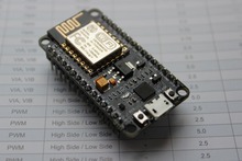
DIY Project Box Enclosure 100x60x25mm
Female to Female Jumper Wires
MicroUSB cable (10′ Cable Recommended)
USB Wall Charger
Project Specific Parts
Microphone Sensor (Get the red one with the small screw)
Suggested Tools:
These are tools needed to build the IoT device in this tutorial, but aren’t necessarily required.
Pliers
Hacksaw
Smoke Detector
Precision Screwdriver Set
Great. Now like I said, its gonna take a while for your stuff to get to you, so in the meantime lets setup some digital infrastructure that your new device will use.
STEP 2: Setup Your IFTTT Account & Recipes
The Wifi Smoke Alarm Notifier, and all of the projects on SimpleIOThings use an internet service called If This Then That (IFTTT). IFTTT executes an action, like sending an SMS or posting a Tweet, when an event takes place. Combinations of events and actions are called recipes, and you can do a lot of cool stuff with IFTTT recipes. For example, I use publically available recipes to automatically tweet my Facebook posts, change my phone wallpaper to the NASA Picture of the Day every morning and send me a smartphone notification if its going to rain tomorrow. Click here to setup an IFTTT account. You’ll need it later to execute actions from your IoT devices.
Using the Maker Channel
For SimpleIOThings projects we’re going to use IFTTT recipes that use the Maker Channel. The Maker Channel allows people to create recipes that interact with DIY devices. The DIY devices you can build using tutorials from SimpleIOThings will send messages over the internet to the IFTTT Maker Channel, which then triggers actions like phone calls and SMS messages. The Maker Channel can also send messages to DIY devices to trigger actions on the device as well.
Follow the link and connect to the IFTTT Maker Channel.
![Maker+Channel+visual[1]](http://www.simpleiothings.com/wp-content/uploads/2015/11/Maker-Channel-visual1-1024x512.png)
Once you connect to the Maker Channel, take note of your “Maker Key,” which is an alphanumeric code that identifies you and your DIY devices when they send web messages. You can jot it down somewhere, or you can always go back to https://ifttt.com/maker to find it.
Using IFTTT Recipes & Organizing Events and Actions
Now that you’re connected to the Maker Channel, lets build some recipes that will trigger cool actions like smartphone notifications, SMS notifications, and phone calls. A greatfeature in IFTTT is the ability to share recipes. I’ve shared my recipe here, but just take a look before you sign up for it.
IFTTT Maker & SimpleIOThings Smartphone Notification Recipe
There are also other cool recipes that you can use. Using IFTTT, your devices can trigger phone calls, emails, and send SMS’s to your friends. Here are links to some more recipe I’ve shared for your convenience.
You can sign up for each recipe using the links. All you need to do is input an event name like “SmokeAlarm” and clicking “Add.”
The reason why I asked you not to sign up for the IFTTT recipes just yet is because I want you to think about how you want to organize your event triggers and recipes. Lets take a look at them in the next section.
Organizing Recipes
Understanding how to organize your IFTTT Maker recipes will help you trigger the desired actions for a given event.
Example 1: Smart Button – Triggering One Action
One of the devices you can build on SimpleIOThings is the Wifi Smart Button. In the default case, I’ve assumed the user is going to use it to report a bad event (like security problems in a store) but it can really be used to send just about any message.
Lets say in this example you are using it to tell you’re significant other that you’re thinking about them. In a case like this, maybe you want to just send your significant other a quick SMS that says “Thinking of you. 😉 ~[Your Name].” You COULD send your partner an SMS, PLUS an email, and a phone call at the press of a button, but that would probably be overkill (depends on the message you’re trying to send I guess). To keep it classy, you could setup an event called “SmartButtonThinkingOfYou” in IFTTT, and have it trigger ONLY the smartphone notification with a sweet message. Later, once your program your smart button to trigger the “SmartButtonThinkingOfYou” event over Wifi, the following process should occur:
- You press the button.
- The Smart Button sends a message (via HTTPS protocol for you nerds out there ;] ) to IFTTT over Wifi with your Maker Channel Key and the Event Name (SmartButtonThinkingOfYou).
- IFTTT receives the message, finds your recipe, and sends a SMS to your partner’s phone carrier.
- Your partner receives an SMS, and smiles.
Example 2: Wifi Smoke Alarm Notifier – Triggering Multiple Actions
Pretty awesome right? However, there’s another project (Wifi Smoke Alarm Notifier) on SimpleIOThings that notifies you when your smoke detector goes off. When this device sends a message to IFTTT, you’d probably want an SMS, Smartphone Notification, Email, and Phone Call to tell you something might be wrong at your house. So for the Smoke Alarm Notifier, you’d probably want to setup an event called “SmokeAlarm” and sign it up for all 4 of those recipes. To do this, you’ll have to sign up for the SMS, Smartphone Notification, Email, and Phone Call recipes with the “SmokeAlarm” event, and then later program your Wifi Smoke Alarm Notifier device to send the “SmokeAlarm” event name when its triggered. Once that’s done, when your device triggers it should result in the following process.
- Smoke Detector goes off.
- Wifi Smoke Alarm Notifier detects the noise from the Smoke Detector alarm.
- The Smoke Alarm Notifier sends a message to IFTTT over Wifi with your Maker Channel Key and the Event Name (SmokeAlarm).
- IFTTT receives the message, finds your recipe, and then:
- Sends a Smartphone Notification
- Sends a SMS.
- Calls your phone with an automated message.
- Emails you.
The bottom line is, you can setup your devices to tell IFTTT that an event occured, and depending on how you’ve configured your IFTTT recipes, the event can trigger a single action, or multiple actions. Some good planning and organization ahead of time will help you trigger the desired actions when an event occurs.
In the case of this particular device, I would recommend utilizing multiple recipes all triggered by an event (named, for example, SmokeAlarm). A smoke alarm going off is an event you want to respond to with some urgency so you probably want to be notified by any means possible.
Testing Recipes
Once you’ve signed up for your recipes you can test your them by going to the Maker Channel, then clicking “How to Trigger Events.” In the following page, enter the event name you created earlier, and click “Test It.” You should get a smartphone notification.
Download the IF App for Android & IOS
To receive smartphone notifications and monitor your IFTTT activity, you can download the IFTTT app on your smartphone. The app can also be used to manage your recipes and channels. You can download the “IF” app from the Android Play Store, or the Apple Itunes Store.
![if_phones-cb185d560c9969938e8ea296bb32413b[1]](http://www.simpleiothings.com/wp-content/uploads/2015/11/if_phones-cb185d560c9969938e8ea296bb32413b1.png)
Okay! We’ve got some really nifty digital infrastructure setup for your project. Soooooo…its gonna take a while before you get all this stuff…so its probably best to bookmark this page and come back after it’s all arrived. See you in a few weeks!
STEP 3: Install Firmware to your Dev Board
Oh hi there! Welcome back. I know its been a while. Maybe the seasons changed in your part of the world. Governments may have risen, switched hands, entered alliances, broken alliances, fallen, and then risen again. Yea…it takes a while to get your stuff. But now that it’s here, lets start building!
Now we’re going to teach the dev board to understand a language. Right now its just a mashup of metal and silicon, but after this step it will understand how to execute commands in a powerful software language called “Lua” (which is in the Python family of computer languages for you nerds out there). Don’t worry though, you won’t be expected to code anything.
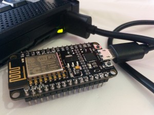
You should connect your dev board to your computer’s USB port using your cable like so. If you have windows computer and an internet connection, the drivers for the board should automatically load. If for some reason it doesn’t you can Google “NodeMCU drivers” and a number of websites with appropriate files should show up.
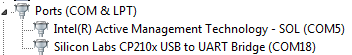
Once your drivers are installed, you’ll also need to determine which communications port the device is connected to. Click your “Start” button and type “Device Manager.” Your device manager should pop up. Click and expand the “Ports (Com & LPT)” menu and you should see your device listed there. In my case, my ESP8266 dev board’s port was set to COM18. For now just take note of that and jot it down somewhere.
Now we have to install “firmware” on to the dev board. This firmware will allow the board to execute programs and understand Lua. To do this we need to download a “flashing” program and the firmware itself. The flashing program will use the firmware file to load firmware onto your board.
The latest versions of the flashing program can be found on github, a popular and trusted site for computer programmers to collaborate on projects. Pick the appropriate flasher based on whether your PC is using a 32-bit or 64-bit operating system.
– 32-bit ESP8266 Flasher
– 64-bit ESP8266 Flasher
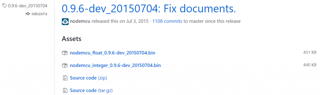
The firmware file can be found on Github. Follow the link below. As of 1/3/2018, the file version that works best is at the bottom of the release page. It is the “integer” version and it will look something like this: [nodemcu_integer_0.X.X-dev_201XXXXX.bin]. A screenshot is also provided below for reference.
There are also some other interesting places to get firmware for the ESP8266 dev board, including a custom firmware builder, however a number of users have reported trouble with the firmware they get from other sources. For now, I recommend sticking with the Github release.
Okay, if you’ve made it this far, you’ve connected your dev board to your PC, obtained the port number, installed your dev board drivers, and downloaded the ESP8266flasher program and the firmware .bin file. Awesome.
Now find your downloaded ESP8266 flasher program and start it. This should pop up:

Change the port number to the port for your ESP8266 Development Board, which you jotted down earlier.
Now click the Config tab, and click the topmost gear on the right hand side.

Once you click the gear icon, use the dialog box to find your firmware (.bin) file in your downloads folder and click “Open.” Then go back to the “Operation” Tab and click “FLASH!” Once the progress bar moves all the way from left to right, your dev board can now understand the Lua language. Congrats!
The last task in this step is to download a program called LuaLoader and use it to connect with your dev board. LuaLoader is a program that can understand the Lua programs your board is running. It also has a lot of handy tools that let you setup wifi, read digital outputs, and so on. Once again, Github has what we need.
– LuaLoader @ Github
Once you’ve downloaded LuaLoader, extract the zip file (if needed), open Lualoader.exe as an administrator. To open as an administrator, right click Lualoader.exe, and then click “Run as an Administrator.” Once open, click Settings, Com Port Settings, and set the port to the one your dev board is connected to and click “OK.”

Then click “Connect” in the menu bar of the Lualoader program. Your ESP8266 dev board should flash an LED for a second, and your Lualoader will show you some strange characters. Congrats, you now have a dev board that is ready to receive a program.

STEP 4: Install Sensor Specific Software to your Dev Board
Great! Now your dev board speaks Lua. Its ready to start communicating with the world. Lucky for you, I’ve already written the software necessary to get your device up and running. Just visit our Downloads page and download SimpleIOThings.zip.
Unpack the .zip file, and then find it. Open “SensorSetup.bat” and it will open a Command Terminal Window. It might look scary, but you only have to input some simple text in response to some questions.

Go through the prompts. Ignore the parts about flashing your dev board (we already did that) and enter your IFTTT Maker Key, the Maker Event name, the sensor’s location info, etc. It will also ask you how many sensor inputs you’d like before an event is triggered. Depending on your use case, you may want to set your threshold lower or higher. When you’ve completed the setup questions, the terminal window will edit your software files (.lua files), and then automatically close.
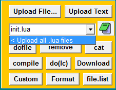
Now go into your Lualoader and click “Upload File…” on the right side menu. Find your unpacked folder and click on any .lua file and click “Open.” Your first .lua program file will upload into the dev board. Now that you’ve set the right directory, click the dropdown menu and click “< Upload all .lua files.” Now ALL of your .lua program files will upload into your dev board.
One last thing. Before we hit restart, setup your wifi network name and password. To do that, enter the wifi network name and password for the network the device will use and click “Set AP.”

Now click “Restart!” If everything went well, you should see “Listening for Sensor Inputs…”

Awesome. That means your ESP8266 dev board is connected to your wifi network and fully programmed. Now we’ll move onto the last step, which is to construct the device.
STEP 5: Build the Smoke Alarm Notifier
All the way back in step 1, we talked about gathering materials. Hopefully now you have everything in hand and your board is programmed. Go ahead and get all your materials together in one space.
Go ahead and unplug your dev board (there is almost no electrical danger to you from touching the dev board while plugged in, but might as well err on the side of safety).
Connecting the Wires
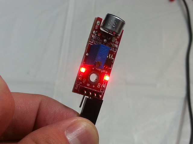
Now, grab the microphone sensor and three female jumper wires. Plug the jumper wires into the “D0,” “GND,” and “+” pins of the sensor. It should look like this.
Now grab your dev board, and observe the names of the pins on the board. Go ahead and plug your jumper wires into the “GND”, “3V3”, and “D2” pins on the right hand side, making sure that “GND” connects to “GND”, “+” connects to “3V3”, and “D0” connects to “D2.” It should look like this:
Believe it or not, you’ve just constructed an Internet-of-Things device! The rest of this tutorial is just some calibration and making the device look good.
Just a quick note for those of you who are interested in the electronics. When setup this way the microphone is powered through the GND and 3V3 pins (via a complete circuit). When the sound around the sensor exceeds a certain level (as determined by the potentiometer, described in the next section), the sensor sends a signal via the “D0” pin to the dev board’s “D2” pin. The ESP8266 dev board registers a change in electrical signal which the chip detects as a sensor input. Pretty cool!
Calibrating Your Microphone Sensor (First Time)
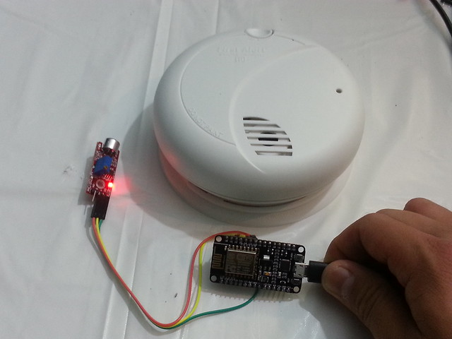
Now that the cables are all connected, go ahead and power your dev board with a microusb cable and place the sensor near your smoke alarm. If everything was connected properly, at least one light should be illuminated on your sound sensor. You’ll notice that the sensor has a small screw on it. Turning this screw calibrates something known as the “potentiometer.” In simpler terms, this screw determines what level of sound will trigger a signal through the “D0” pin from the sensor to the dev board. If you turn the screw clockwise, a lower level of noise (quieter) will cause the sensor to send a signal to the ESP8266 Development Board. If you turn the screw counter-clockwise, louder noises are required to trigger a signal to the development board. You can also visually confirm when your sensor is sending a digital signal to the dev board because a second LED light will illuminate on the board. Use the 2nd LED and the screw to set the potentiometer to a level where normal ambient noise and conversation will not trigger a signal to the dev board (i.e. 2nd LED does not light up).
Now go ahead and test your smoke alarm (most smoke alarms feature a “test” button which will trigger a limited number of alarms. (Note: The alarm will be loud. If you’re sensitive to noise, it might be a good idea to wear hearing protection). The 2nd LED should light up when the alarm is ringing. Now turn the screw counter-clockwise until the 2nd LED does not light up when the alarm is ringing. Once you get there, stop, then turn the screw clockwise until the 2nd LED is just lighting up again. Stop turning the screw and keep this configuration until later. Modifying Your Enclosure Okay, now lets move onto the enclosure. Actually, the enclosure is nice to have, but not 100% necessary. You could put this project inside of a soap case or a pencil box, or other common household objects. Just make sure the case is not flammable, and isn’t conductive (i.e. not metal). At about a dollar though, I think its nice to have a professional looking enclosure, so I think its worth buying one. The enclosure needs a place for wires to come out of the back, and for sound to enter through the front. I sawed a piece of the back of the enclosure out, and used pliers to tear off some of the enclosure so sound could enter through the front. Here’s some pictures of how I modded my enclosure.
![22589879676_cf4647a36b_k[1]](http://www.simpleiothings.com/wp-content/uploads/2015/11/22589879676_cf4647a36b_k1-300x225.jpg)
![22602474682_295c29c4af_k[1]](http://www.simpleiothings.com/wp-content/uploads/2015/11/22602474682_295c29c4af_k1-300x225.jpg)
![22616031985_c940136ff1_k[1]](http://www.simpleiothings.com/wp-content/uploads/2015/11/22616031985_c940136ff1_k1-300x225.jpg)
There are other ways to do this, such as using a soldering iron to melt holes into the plastic. How you choose to house your electronics and modify your enclosures is up to you. The way I did it with a saw is kind of “hacky” (pun intended) but worked for me. Alright, now you can put your electronics into the enclosure. Plug your usb cable into the dev board, and make sure your jumper wires are well positioned, but don’t close the project box just yet. Calibrating Your Microphone Sensor (Second Time) Now that your sensor is inside the enclosure, you will need to set your microphone sensor to be triggered by lower sound levels (since the enclosure will dampen some of the Smoke Alarm noise). Turn the screw by a half clockwise turn, then close the project box. Orient it towards the smoke alarm similar to how it will be oriented when finally installed, then and test the alarm. If its possible, try to observe if the 2nd LED is triggered. If that’s not possible, connect the device to your PC, and use LuaLoader’s readout. By now, the software you’ve uploaded should be working and displaying “sensor input counted” if the smoke alarm is triggering a signal. 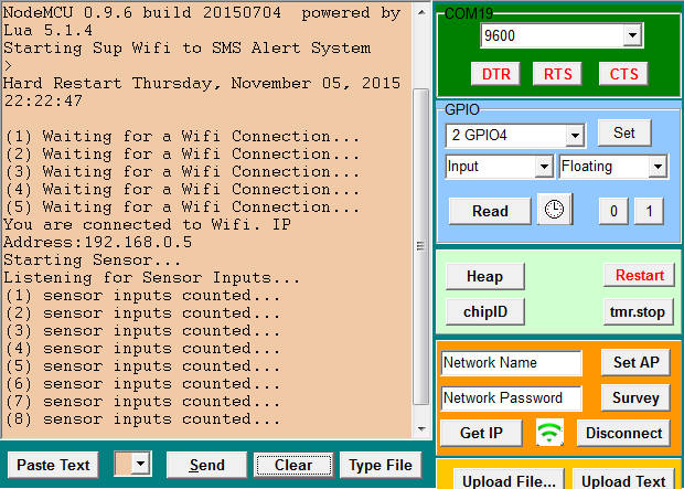 If its not sending a signal to the dev board, turn the screw clockwise by another half turn, close the project box, and read again. Repeat this process until the smoke alarm triggers a signal while inside the enclosure.
Step 6: Final Installation
The last thing you’ll want to make sure is that the Wifi Smoke Alarm Notifier works once its installed on a wall or ceiling near your Smoke Alarm. I used some push pins to make sure both the enclosure and the cord are secure, and look neat. Of course, I tested it again once it was up on the wall, and it’s been there ever since, vigilantly waiting 24/7 for an alarm to sound. 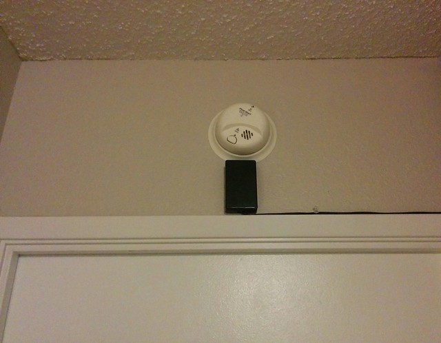
And we’re done!
Your Wifi Smoke Alarm Notifier is now up and running. Give it a test run and it should trigger whatever you’ve set it up to do, whether that’s a smartphone notification, SMS, phone call, email, etc.
I hope you enjoyed building a super simple Internet-of-Things device. Hopefully you will be able to use it for something useful, or use it to do something fun. If you enjoyed this tutorial, consider donating at the link below. Thanks for reading!
SimpleIOThings • November 6, 2015
Philippe December 29, 2015 - 9:32 am
Hi!
Just a short e-mail to tell you that i have followed your tutorial and build up the device: it works perfectly!! and I am not an expert….By now, I am testing it with a message sent by pushbullet.
Just one question: if I would like to modify the Lua files (to change the threshold level for ex):
Can I use again the .bat file, modify the parameters and load again all files with LuaLoader?
Are Lua files will be removed and replaced automatically by the new one?
Once again, very nice job !!
Kind regards,
Philippe
SimpleIOThings January 4, 2016 - 2:54 am
Hi Philippe! Yes, the .bat file can be used over and over again to reconfigure the same chip. LuaLoader will overwrite files of the same name, and overwritten files with the new values will adjust the behavior of the chip/device to your specifications. If you feel hesitant about that, feel free to wipe the chip using LuaLoader and start all over. Takes about the same amount of time. I’m very happy to hear that people used this tutorial to make something cool. Let me know how you’re using your devices!
Philippe January 4, 2016 - 7:12 pm
Hi !
First of all I would like to wish you all the best for 2016 !!
Thank you for your so fast answer! OK for the use of the .bat file! Good idea to wipe the ship before, probably more clean procedure than to rewrite!
I have now tested tested the device for few days and I have by now just one issue: sometime I need to turn on /off the power because the device is not working…Like if it has lost its connection. Each time I do that, it works again immediately! Do you have an idea on what is going wrong? Did you also observe this issue?
I have read somewhere that the quality of the charger can be a problem for ESP8266. My charger specification: 5 V, 1000 mA: is it enough?
I would like to try to solve this issue as I would like to use the device as you, for a alarm detection!!! It need to work all the time….!!
Hope to hear from you a solution! 🙂
Kind regards
Philippe
SimpleIOThings January 8, 2016 - 5:34 am
From my experience I had problems only with the dev boards that had CH340 chipsets. There are several variants of the ESP8266 dev board. There is a 0.9 version (which I have no experience with) and also a CH340 chipset variant (which I don’t recommend). The dev boards I link to use the CP2102 chipset, which in my opinion is more robust and less prone to restarts. Another issue I sometimes observed is that notifications via IFTTT can be laggy (by a minute or two), which I think may be service issues on their side. 5V at 1000 mA is fine, and I’ve never had any problems using any microUSB smartphone charger to power the device. HOWEVER, some cheap microusb cables are not great for connecting the chip to a PC. In my experience, OEM cables from your smartphone, or heavy weight microUSB cables (28/20 AWG or 28/24 AWG) are better for programming your chip. A better cable supplying your power may help your device stability as well. That’s everything I can think of to help you troubleshoot.
Philippe January 9, 2016 - 7:13 pm
Hello!
Thank you for your message.
I have a CP2102 chipset on my ESP8266 dev board! Good! However, from my last message, I have no problem with the ESP8266…..Each time I trigger the microphone, I have a notification! And I have of course changed nothing….! Hope that it will stay like this! I will take care to use a good cable! Regarding IFTTT, I have observed exactly the same issue….One time I had received the message more than 30 min after…As you mentioned, this is probably from their side. Generally, I am using Pushingbox to send notification to android or IOS Phone, it works very well with no important lag time. To my point of view, Pushingbox is quite easy to use. Do you know it? If not, have a look to the website!
Thank you again for all your details!
I am preparing another message with an idea on how to use your device…But It will need your help as I am not at all an expert in Lua…..
See you soon!
Dennis April 7, 2017 - 11:42 pm
love your project and can’t wait to do my own with slight variation. I have a (dry) contact closure available on a sump pump watchdog that I want to connect to the ESP8266 instead of microphone module. I believe your program will work OK to recognize the “event” (unless the programmed input needs to change?), but I don’t know the pin-outs for the ESP8266 – can it recognize a contact closure or does it need to be a pull-up/pull-down powered input?
josef January 16, 2016 - 5:01 pm
Hey, thanks for a fun project, everything works great, except that the delay time between the smartphone nots don´t works for me, what do you think I did wrong? Sincerely, / Josef.W
Kergad March 16, 2016 - 5:14 am
Thanks again SimpleIOThings for this AMAZING tutorial! Even for someone with low competency in hardware everything looks so simple!
I’m waiting to get my devices to do my first test but in fact I’m looking for to trigger different level of dB. Coud it be possible to modify this device with a sound sensor capable to detect multiple dB and send different notification?
Tina May 19, 2016 - 4:06 pm
I’m not familiar with dev boards, once the program is flashed to the dev board will it communicate directly with the router or does the computer need to remain on in order for the message to be sent?
SimpleIOThings October 9, 2017 - 1:34 pm
The dev board has a wifi chip that should be able to communicate with most 2.4GHz wifi networks given the username and password. Try plugging it into a typical phone charger (5 volts, 1 Amp).
Adam September 8, 2016 - 1:53 am
Hi, I was just wondering i’m doing this for a school project and I was thinking could I solder regular wires instead of using female jumper wires?
Thanks, Adam
SimpleIOThings October 9, 2017 - 4:34 am
Soldering would definitely work. This blog was written so the projects could be completed easily, but soldering would certainly help keep your connections more secure.
adam curlewis September 19, 2016 - 12:36 am
Thanks for making this website and this has been extremely helpful to me and i wanted to thank you but i seem to have come to a problem with the wifi stage on lua loader because after i enter all of the details nothing happens after clicking set AP and doing a reset doesnt work either.
Thanks, Adam
dev February 23, 2017 - 9:15 pm
hello,
the project looks great however the .zip file download no longer works, do you have the copy i can use or know how and what’s written there?
https://www.dropbox.com/s/5ow3c76l7p8jfni/SimpleIOThings.zip?dl=0
Mathil March 2, 2017 - 8:05 pm
Very cool. I’ve ordered my parts and will be trying this out ASAP. Quick question: would it it be feasible to have the ESP8266 board powered by a battery? Unfortunately my smoke alarms are installed in areas that would look horrendous with a usb cable running to them. Any suggestions?
Thanks for your time!
dev March 9, 2017 - 3:50 pm
Very good, thanks a lot, i will definitely paypal donate 🙂
Martin Hill May 5, 2017 - 9:04 am
Also, just realised that my device is broadcasting as BSSID of “simpleiothings sensor setup” even when it’s all fully set up and running in a production environment.
Is it supposed to be doing this? Is it meant only for debugging, or necessary for production env too?
mohammad April 18, 2018 - 2:14 pm
hello
can i use a smoke sensor connected to the devboard directly instead of microphone sensor and if the answer is yes should i modify the lua files or anything else i should do?
SimpleIOThings February 14, 2019 - 10:23 am
Hey Mohammad, I considered a smoke sensor at some point, but I’d have to check what kind of signal output you get from the sensor and if it’s a usable signal for the program that runs on the chip. Since the chip requires a digital, binary signal (0 or 1) it may not work if the smoke sensor provides and analog output. Which sensor were you thinking about using.
Anil February 13, 2019 - 8:58 pm
Hello,
Thanks for a great article. This got me started recently. I know I am pretty late in the game and that you may not be monitoring this site any more, but, I will take a chance.
I am a hobbyist programmer. I need a few clarifications about the “debounce” function:
1) Shouldn’t the “last” variable be global in scope or else it will get initialized to 0 in each call to “debounce”?
2) What is the purpose of the “bounceCheck” variable in the “debounce” function? It does not seem to be getting used anywhere.
Sincerely,
Anil